"Pickup" sensors
| Vehicle | Crank teeth | Crank sensor | Crank edge | Cam teeth | Cam sensor | Cam edge |
|---|---|---|---|---|---|---|
| 1ZZ/2ZZ | 36-2 | Hall Effect | Falling | 3 | Hall Effect | Falling |
| 2JZ VVTi | 36-2 | VRT | Falling | 3 | VRT | Falling |
| 350Z/370Z | 36-2 | Hall Effect | Falling | 3 | Hall Effect | Falling |
| Civic 88-00 | 12 | Hall Effect | Falling | 1 | Hall Effect | Falling |
| Civic 02-15 | 12+1 | Hall Effect | Falling | 4+1 | Hall Effect | Falling |
| Evo 7-9 | 2 | Hall Effect | Falling | 2 | Hall Effect | Falling |
| Evo 10 | 36-2 | VRT | Rising | 3 | Hall Effect | Falling |
| Miata 90-05 | 4 | Hall Effect | Falling | 1 | Hall Effect | Falling |
| Miata 06-15 | 36-2 | VRT | Rising | 3 | Hall Effect | Falling |
| Subaru EJ20/25 | 36-2 | VRT | Rising | 3 | Hall Effect | Falling |
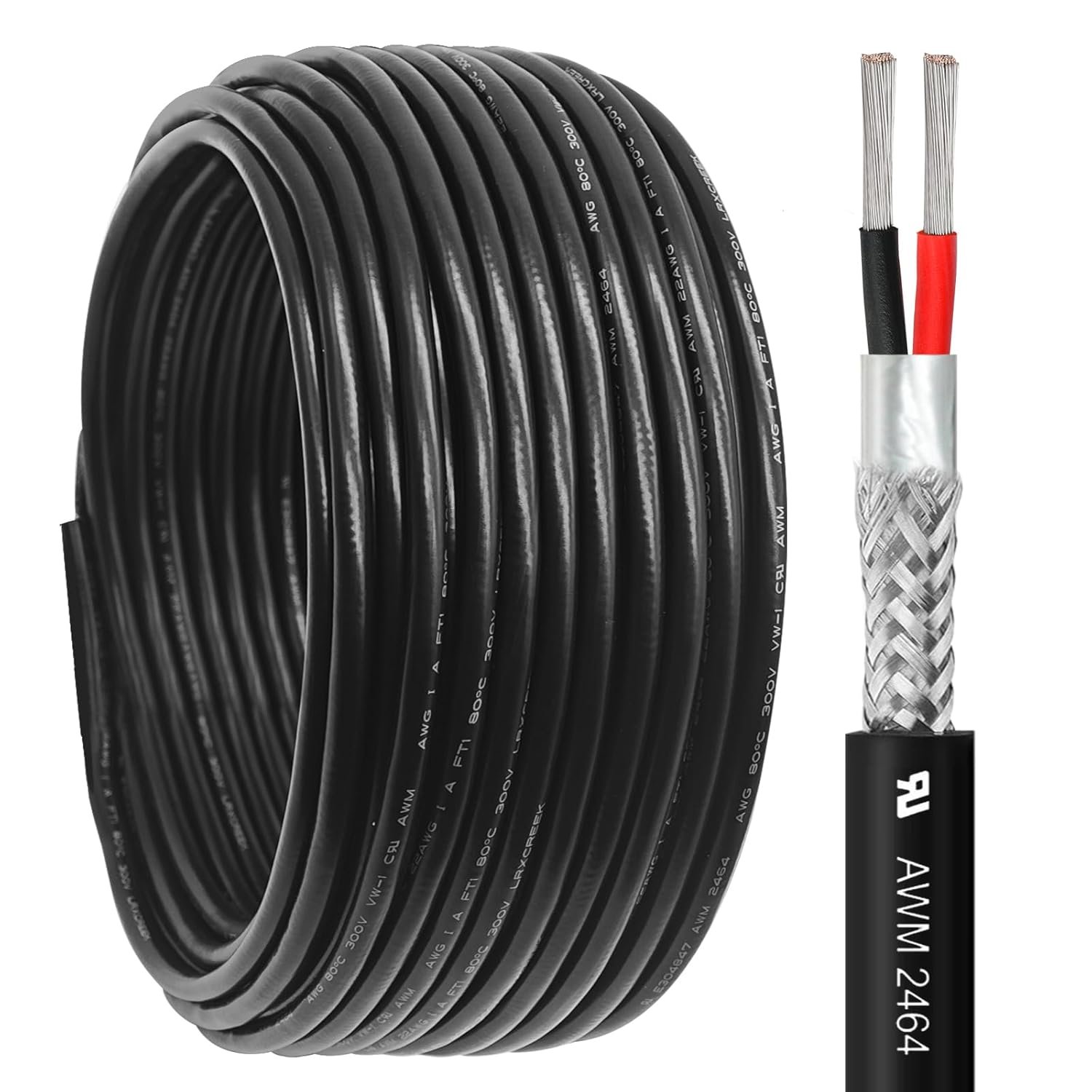
20/2 Shielded Wire 30FT 20 Gauge 2 Conductor Wire, UL2464 20 AWG Chain CNC Tinned Copper Cable for CNC Router Machine, CNC Spindle, Microphone, 3D Printer
Buy on Amazon As an Amazon Associate I earn from qualifying purchases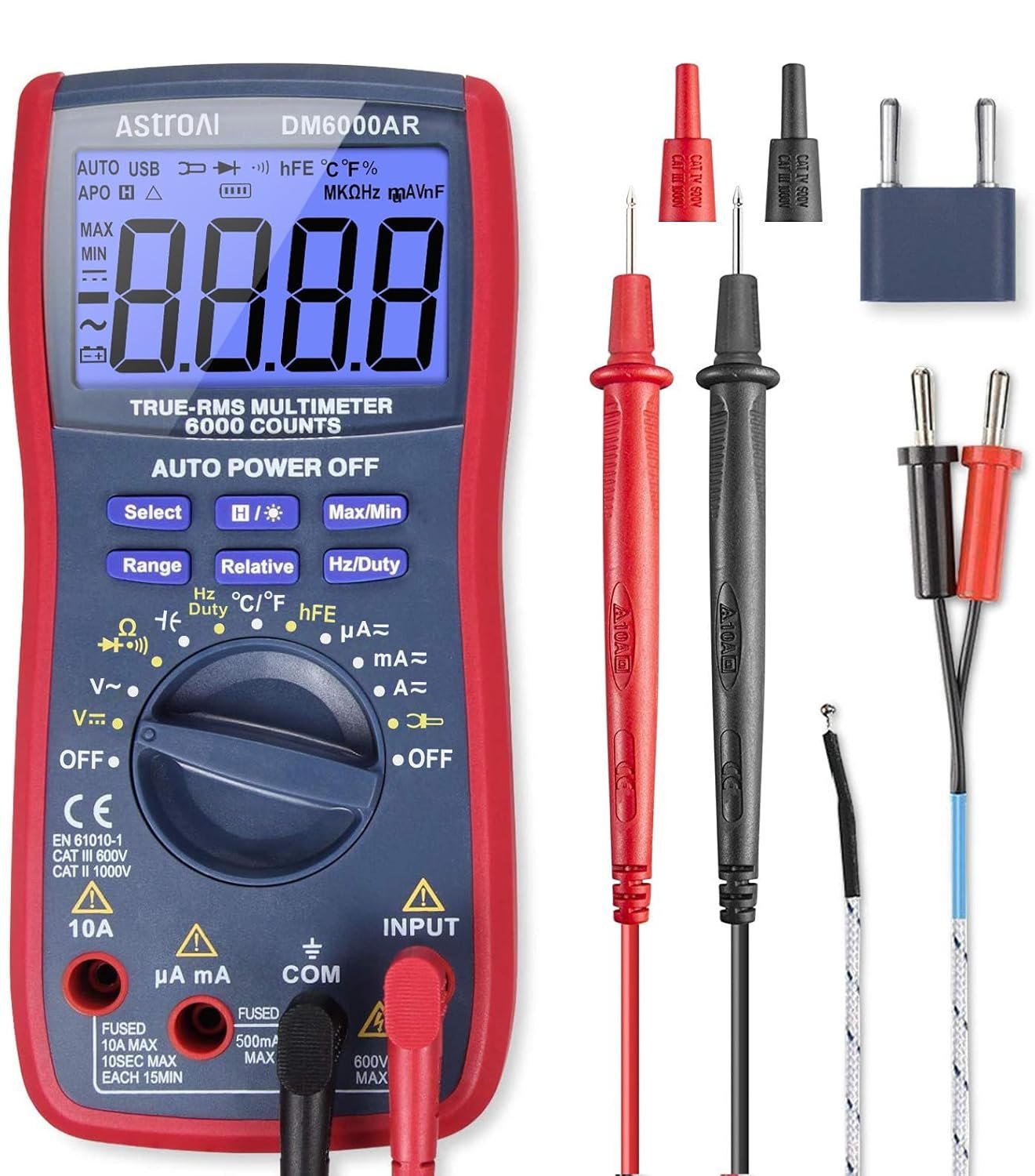
AstroAI Digital Multimeter and Analyzer TRMS 6000 Counts Volt Meter Ohmmeter Auto-Ranging Tester; Accurately Measures Voltage Current Resistance Diodes Continuity Duty-Cycle Capacitance Temperature
Buy on Amazon As an Amazon Associate I earn from qualifying purchases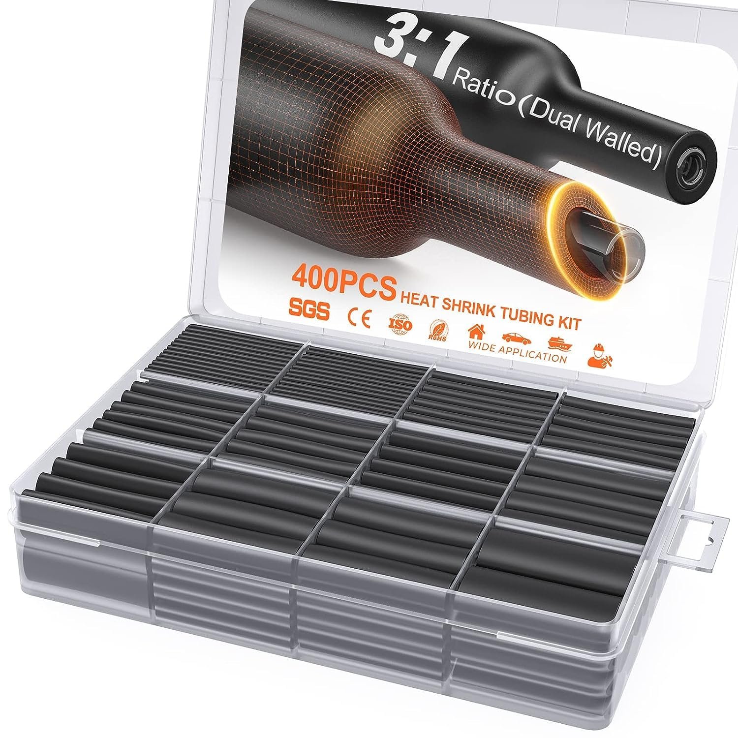
400 Pcs Heat Shrink Tubing Kit-3:1 Ratio Adhesive Lined,Marine Grade Shrink Wrap - Industrial Heat-Shrink Tubing - Black
Buy on Amazon As an Amazon Associate I earn from qualifying purchases
SVAAR 380PCS Non Insulated Butt Connectors Kit Butt Splice Connector Uninsulated Wire Splice Connectors for 26 to 6 Gauge Wire Marine Grade Tinned Copper Seamless Barrel Crimp Butt Splice Terminals
Buy on Amazon As an Amazon Associate I earn from qualifying purchases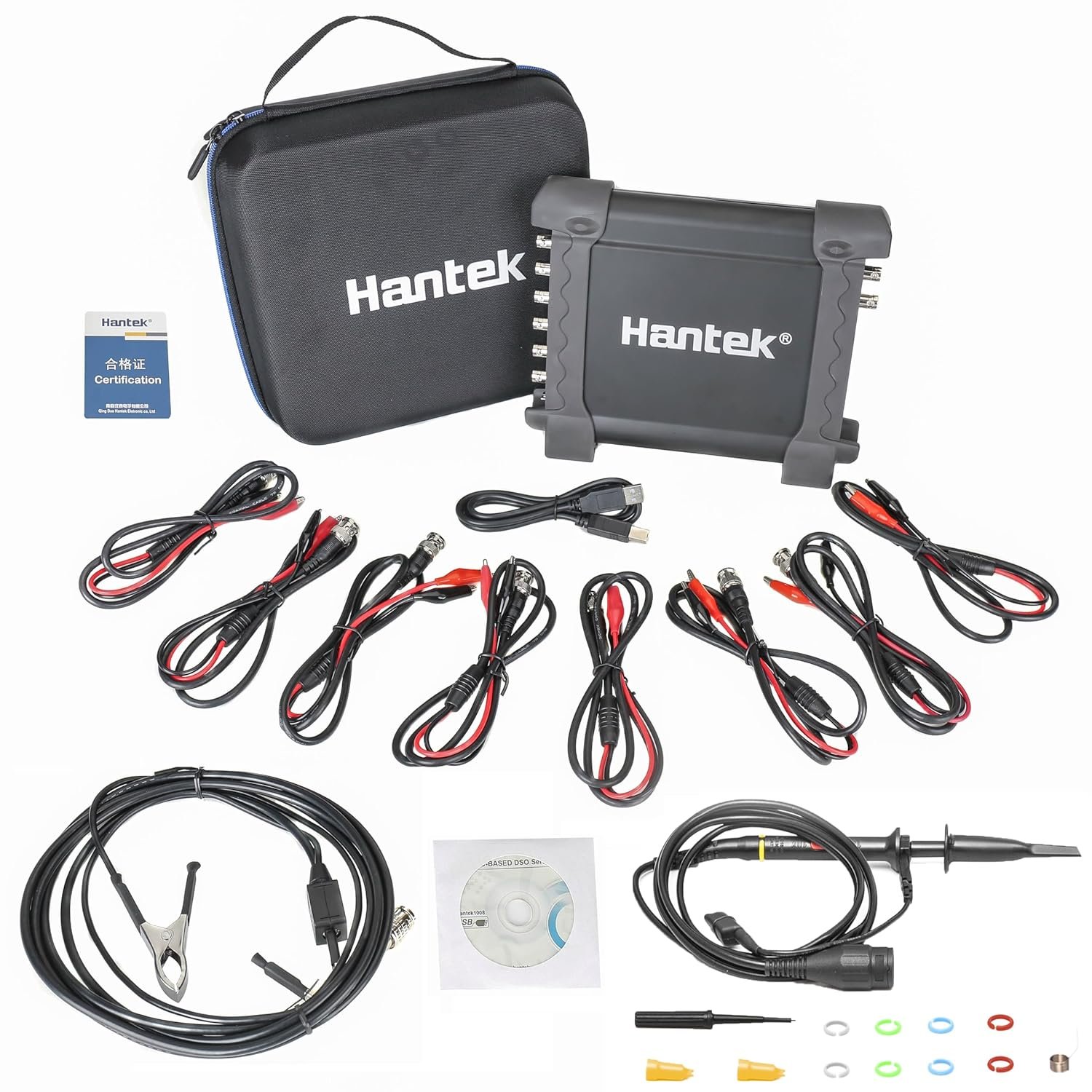
Hantek 1008C PC USB 8CH Automotive Diagnostic Digital Oscilloscope/DAQ/Programmable Generator
Buy on Amazon As an Amazon Associate I earn from qualifying purchases
20/2 Shielded Wire 30FT 20 Gauge 2 Conductor Wire, UL2464 20 AWG Chain CNC Tinned Copper Cable for CNC Router Machine, CNC Spindle, Microphone, 3D Printer
Buy on Amazon As an Amazon Associate I earn from qualifying purchases
AstroAI Digital Multimeter and Analyzer TRMS 6000 Counts Volt Meter Ohmmeter Auto-Ranging Tester; Accurately Measures Voltage Current Resistance Diodes Continuity Duty-Cycle Capacitance Temperature
Buy on Amazon As an Amazon Associate I earn from qualifying purchases
400 Pcs Heat Shrink Tubing Kit-3:1 Ratio Adhesive Lined,Marine Grade Shrink Wrap - Industrial Heat-Shrink Tubing - Black
Buy on Amazon As an Amazon Associate I earn from qualifying purchases
SVAAR 380PCS Non Insulated Butt Connectors Kit Butt Splice Connector Uninsulated Wire Splice Connectors for 26 to 6 Gauge Wire Marine Grade Tinned Copper Seamless Barrel Crimp Butt Splice Terminals
Buy on Amazon As an Amazon Associate I earn from qualifying purchases
Hantek 1008C PC USB 8CH Automotive Diagnostic Digital Oscilloscope/DAQ/Programmable Generator
Buy on Amazon As an Amazon Associate I earn from qualifying purchasesPickup Sensors: VRT vs. Hall Effect
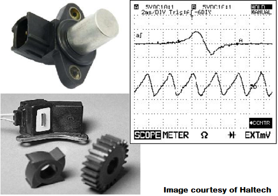
There are two main types of pickup sensors: VRT (Variable Reluctance Transducer) and Hall Effect sensors. They are both shaped similarly.
Both sensors will be positioned within a few millimeters from a toothed wheel known as a "tone ring", "reluctor wheel", or simply called a gear or pickup wheel. The ring is a metal toothed wheel that provides position or movement data that is read by the Hall Effect or Reluctor.
The VRT sensor is an electromagnet (copper wrapped around iron) that sits near a gear tooth. When it passes near the gear tooth it produces a voltage spike. The ECU interprets these spikes as engine speed/position, wheel speed, or gear speed.
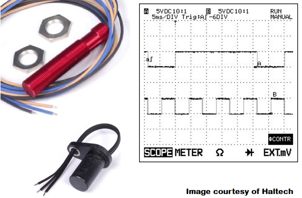
The Hall Effect sensor contains a transistor and electromagnet inside, and when metal passes near it the field is interrupted and the circuit opens. This produces an on-off signal.
When each sensor is used on an engine, position data is important — the toothed wheel will have one or two teeth missing so the ECU can determine engine position for timing.
On a transmission or driveshaft where speed is the thing being measured, there should not be a tooth missing.
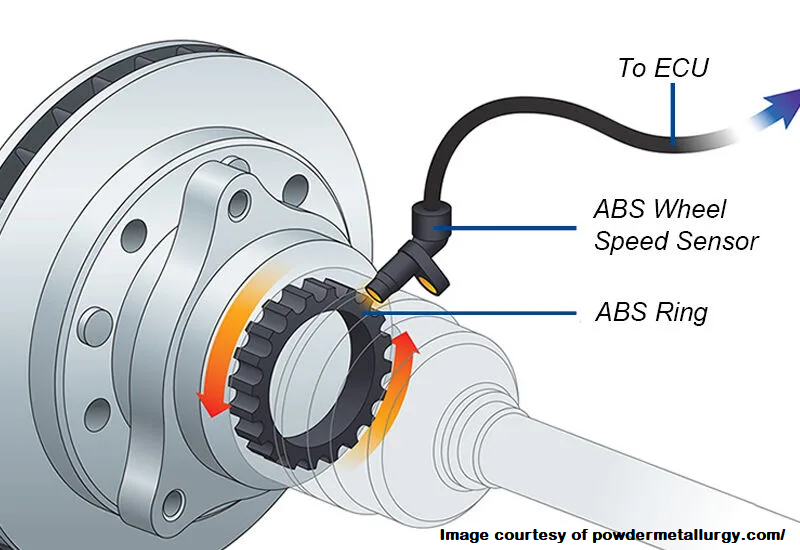
Common Applications: Wheel Speed (ABS and Traction Control), Transmission Gear speed, Engine speed, Turbo Speed, etc.
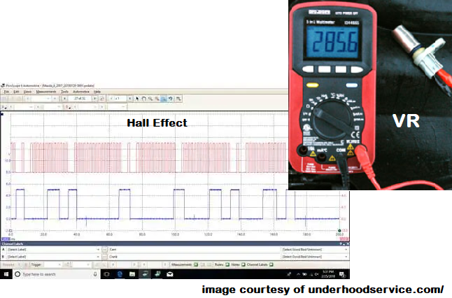
• VRT (Reluctor): Analog voltage spikes from gear teeth passing — simple, passive, no power needed
• Hall Effect: Digital on/off square wave — requires +5V/+12V power, more precise for position
• Missing tooth: Required for engine crank/cam sync (TDC/position reference)
• No missing tooth: Pure speed measurement (transmission, wheels, turbo)
Both read tone rings — choose based on ECU input type (analog vs. digital) and application.
TWO WIRE Reluctor (VRT) sensors
VRT (Variable Reluctance) Sensor Wiring & Configuration
Wiring: VRT sensors are generally 2-wire. Polarity matters, but it will sometimes still operate with the wires reversed — just not perfectly.
The sensor wire should be shielded and the shielding grounded at one end only — join the shield to your other sensor grounds.
18 to 20 AWG 2-conductor shielded wire works well for this application.
Toyota has been known to join the ground wires for cam and crank pickups together. In custom engine applications, separate these, but always refer to your aftermarket ECU's wiring diagram for specific information.
Configuration: These can usually be set up with "falling edge" and no pullup enabled.
Consult your sensor datasheet and ECU wiring diagram for vehicle-specific wiring.
You may see an "arming voltage" or similar setting in your ECU. The ECU will not use the signal from the sensor until it rises above the arming voltage — this is useful if you have interference at low sensor speeds (prevents false triggers during cranking or low RPM).
• 2-wire: Polarity important (try reversing if no signal, but correct is best)
• Shielded cable: 18–20 AWG 2-conductor, ground shield at ECU/sensor ground end only
• Toyota OEM: Often shared grounds for crank/cam — separate in custom builds
• Trigger: Usually "falling edge" + no pullup
• Arming voltage: Raise if low-RPM noise/false triggers occur
Always double-check ECU manual — proper shielding + clean grounding = rock-solid crank/cam signals.
HALL EFFECT sensors
Hall Effect Sensor Wiring & Configuration
Wiring: Hall Effect sensors can be 2 or 3 wire, but are mostly 3 wires. Polarity matters.
The sensor signal and voltage wires should be shielded, and the shielding connected to the sensor ground on your ECU.
The sensor ground for this sensor can be connected via the shielding of your shielded wire.
Wire gauges can be 18 or 20 AWG depending on the amp draw — consult your datasheet or mimic the OEM wire gauge.
Identifying: This sensor has a similar shape to the VRT and can be mistaken for it. 2-wire Hall Effect sensors are easily mistaken for VRT-style pickups.
Configuration: These can usually be set up with "falling edge" and pullup enabled.
Consult your sensor datasheet and ECU wiring diagram for vehicle-specific wiring.
You may see an "arming voltage" or similar setting in your ECU. The ECU will not use the signal from the sensor until it rises above the arming voltage — this is useful if you have interference at low sensor speeds (helps filter noise during cranking or low RPM).
• Wires: Mostly 3-wire (+V, signal, ground); polarity critical
• Shielding: Signal + voltage wires shielded, ground shield at ECU/sensor ground end
• Ground: Can use shield as ground path
• Gauge: 18–20 AWG typical — match to current draw or OEM spec
• Trigger: Usually "falling edge" + pullup enabled
• Arming voltage: Raise if low-speed noise/false triggers occur
Double-check ECU manual — clean shielded runs + correct pullup/edge = reliable digital crank/cam/wheel signals.
Testing and troubleshooting
Testing VRT & Hall Effect Sensors — Tools & Methods
Oscilloscope (if you have access to one) or an OBD2 scantool with either a voltage readout or graphical interface to interpret sensor data for a Hall Effect.
Physical inspection & continuity check: If you don't have access to an o-scope, verify your wiring first by disconnecting the sensor and the appropriate plug on your ECU, then test continuity with a multimeter (only for VRT).
Once you've determined that you have continuity, reconnect your sensor and check for a signal again via your OBD-2 scanner or o-scope.
OBD2 Scantool method: Connect your scantool to the diagnostic port, and find the data screens (or sensor data) portion of your scantool. Rotate your wheel with the car off the ground (or turn the engine over) while simultaneously looking at your scantool for voltage readings or signal patterns.
Multimeter method: This can only be done on the VRT sensor. Put each probe end on the sensor on the low resistance setting. Spin the wheel or engine, and watch for resistance changes. Compare the readings to your car's repair manual.
You can perform continuity tests on a Hall Effect sensor, and you can measure voltage on the positive wire from the ECU, but there is no resistance check that can be performed on Hall Effect sensors.
• Preferred: Oscilloscope → see full waveform shape & timing
• OBD2 scanner: Live voltage or PID graph while spinning wheel/engine
• Multimeter (VRT only): Resistance swings as teeth pass; continuity on wiring
• Hall Effect: Check +V supply from ECU, continuity on signal/ground; no resistance test
• Always: Disconnect/reconnect to rule out wiring faults first
No signal? → Confirm power (Hall), polarity (both), shielding/grounding, and missing-tooth alignment on tone ring.
Wiring
Hall Effect vs. VRT Sensor Wiring Summary
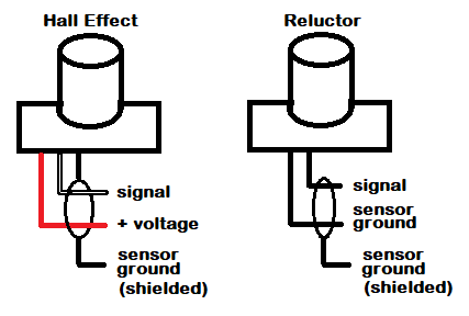
Hall Effect sensors generally have 3 wires:
- Voltage feed (+5V or +12V from ECU)
- Sensor ground
- Signal wire (digital square wave output)
The sensor ground can be used as the shield if you purchased a 2-conductor shielded wire.
Variable Reluctance Transducer (VRT) sensors will have 2 wires.
They don't receive a voltage like the Hall Effect does. They generate a voltage spike when metal passes in front of the pickup, which registers on the ECU.
Technically both wires are "signal" wires, but polarity can matter.
• Hall Effect: 3-wire (+V, ground, signal) — powered, digital on/off
- Ground can double as shield connection
• VRT (Reluctor): 2-wire (signal +, signal -) — passive, analog spikes
- No external power needed
- Polarity usually important (reversing may reduce amplitude or invert signal)
Use shielded cable for both — ground shield at one end (typically ECU side) to reject noise.
Extra Information
VRT & Hall Effect Sensor Reliability & Shielding Notes
VRT wheel speed sensors sometimes have shielding around the tone-ring/reluctor-ring. If this shielding is damaged, it can provide erratic results to the ECU (noise, dropouts, or false readings).
Hall Effect sensors are slightly more complex than VRT sensors. For this reason they are generally not as reliable, though they can produce a cleaner on-off style signal than the VRT sensor (digital square wave vs. analog sine-like spikes).
In a 2-wire Hall Effect sensor, there is a voltage wire and a ground wire. The ground wire is also the signal wire.
(Note again that this is not a common sensor — most Hall Effect sensors are 3-wire with separate +V, ground, and signal lines.)
• VRT: Simpler, passive, very reliable — but analog signal can be noisy if shielding damaged
• Hall Effect: More complex electronics → slightly lower long-term reliability
- Cleaner digital output (on/off) — easier for ECU to read precisely
- 3-wire most common (+V, ground, signal)
- 2-wire rare: Voltage + shared ground/signal — polarity critical
• Tone ring shielding: Inspect for damage on wheel speed VRTs — fixes erratic ABS/traction issues
Choose based on ECU compatibility — VRT for simplicity, Hall for cleaner signal when supported.