2JZ ECU Pinouts
2002-2005 Lexus IS300 Manual and Automatic
NOTE: All colored cells below only show primary wire color, they do not show the stripe. Please see the "Text" color cell adjacent to the color.
| MAF wiring | |||||
| ECU | Color | Purpose | |||
| A5 | B-R | Switched power fm ECU. All VSV/O2/transponder/MAF | |||
| A6 | B-R | ||||
| B34 | BR | Gnd: P/S press.TPS.PPS.MAF.Vapor | |||
| C26 | L-W | MAF | |||
| C27 | G-B | MAF | |||
| C32 | L-B | MAF | |||
| Pin | ECU | Igniter wiring | |||
| Color | Purpose | ||||
| 1 | B-R | Ignition coil 1 | |||
| 2 | G | Ignition coil 2 | |||
| 3 | D7 | BR | Gnd F. Intake. For shields | ||
| 4 | C7 | B-L | IGF | ||
| 5 | E26 | B-Y | IN3.to IGNpin 10 | ||
| 6 | E27 | B-R | IN2.to IGNpin 2 | ||
| 7 | C13 | GR-B | IN1 | ||
| 8 | |||||
| 9 | B-W | Power from IGN Sw. Joins coil- | |||
| 10 | B | Ignition coil 3 | |||
| TPS wiring | |||||
| ECU | Color | Purpose | |||
| B35 | L-Y | 5V Positive | |||
| E25 | W-R | TPS VTA1 | |||
| E24 | G-Y | TPS VTA2 | |||
| B34 | BR | Gnd: P/S press.TPS.PPS.MAF.Vapor | |||
| Pin | ECU | Throttle Control Motor | |||
| Color | Purpose | ||||
| 1 | E2 | R | Throttle (TCM M-) | ||
| 2 | E3 | W | Throttle (TCM M+) | ||
| 3 | E10 | R-W | Throttle (TCM C+) | ||
| 4 | E9 | Y | Throttle (TCM C-) | ||
| Pin | ECU | Power Steering Pressure sensor wiring | |||
| Color | Purpose | ||||
| 1 | B34 | BR | Gnd: P/S press.TPS.PPS.MAF.Vapor | ||
| 2 | C23 | V | P/S pressure signal | ||
| 3 | B35 | L-Y | 5V positive | ||
| Pin | ECU | Crank Position Sensor wiring | |||
| Color | Purpose | ||||
| E31 | (B-W) | Crank Sensor | |||
| E32 | (L) | Cam/Crank (-) joined | |||
| A | M | ||||
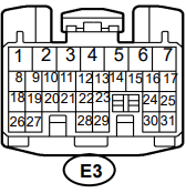
| Pin | Color | Purpose | |||
| E3 Connector "A on diagram" | 1 | W-B | Gnd. Left Fender Apron | ||
| 2 | W-B | Gnd. Left Fender Apron | |||
| 3 | |||||
| 4 | B-Y | Power. EFI Relay, pin 5 | |||
| 5 | B-R | Switched power. All VSV/O2/transponder/MAF | |||
| 6 | B-R | ||||
| 7 | L-W | ETCS fuse | |||
| 8 | B-L | Stop light switch | |||
| 9 | |||||
| 10 | |||||
| 11 | B-Y | to unlock warning | |||
| 12 | B | fm clutch start/park neutral | |||
| 13 | B-O | EFI relay signal (+) pin 1 | |||
| 14 | G-Y | Circuit opening relay (-) pin2 | |||
| 15 | G-R | Fuel Pump Relay signal (-) | |||
| 16 | L-W | From A/C comp relay | |||
| 17 | B-O | Ignition Switch 7.5A fuse | |||
| 18 | LG-R | Ambient air temp (+) A/C | |||
| 19 | |||||
| 20 | L | Fm airbag sensor | |||
| 21 | |||||
| 22 | |||||
| 23 | |||||
| 24 | |||||
| 25 | L-Y | A/C dual pressure switch | |||
| 26 | R-W | fm multi display/airbag sens | |||
| 27 | |||||
| 28 | |||||
| 29 | |||||
| 30 | W | Security Indicator Light | |||
| 31 | G-B | Transponder key pin 2 | |||
| Pin | ECU | Cam Position Sensor wiring | |||
| Color | Purpose | ||||
| E29 | (G) | Cam Sensor | |||
| E32 | (L) | Cam/Crank (-) joined | |||
| A | M | ||||
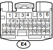
| Pin | Color | Purpose | |||
| E4 Connector "B on diagram" | 1 | ||||
| 2 | R-L | CEL (malfunction indicator) | |||
| 3 | R-W | Fm multifunction Fm airbag | |||
| 4 | G-W | Fm Stop Light SW | |||
| 5 | GR-R | STFU (shift up??) | |||
| 6 | GR-G | STFD (shift down??) | |||
| 7 | G-B | O2 B1S2 heater | |||
| 8 | R-W | O2 B2S2 heater | |||
| 9 | G | To Skid Control | |||
| 10 | P | VSV #8 pressure sw valve | |||
| 11 | W-L | To Speedo | |||
| 12 | Y-G | A/T LL position | |||
| 13 | Y-R | GR-B A/T Drive Position. Y-R 02 M/T | |||
| 14 | LG-B | A/T To shift lock control ECU | |||
| 15 | G-Y | A/T Transmission control switch | |||
| 16 | B | Tach, fm igniter pin9 | |||
| 17 | (W) | O2 B2S2 signal | |||
| 18 | R-Y | Fm Skid ECU | |||
| 19 | P | To Skid Control (L-B[pin30] on 02 M/T) | |||
| 20 | O | Multiplex - Theft deter. | |||
| 21 | O | Multiplex - Theft deter. | |||
| 22 | LG | Datalink connector 3 pin15 | |||
| 23 | P-B | Transponder key pin 4 | |||
| 24 | V | Transponder key pin 3 looks brown | |||
| 25 | L-W | V# 7 Vapor Pressure sensor | |||
| 26 | |||||
| 27 | |||||
| 28 | (W) | O2 B1S2 signal | |||
| 29 | W-G | Fm Skid ECU | |||
| 30 | L-B | To Skid Control(P[pin19]on 02 M/T | |||
| 31 | L-R | Cruise control switch | |||
| 32 | L-W | Pedal Position Sensor VPA2 | |||
| 33 | P-L | Pedal Position Sensor VPA1 | |||
| 34 | BR | Gnd: P/S press.TPS.PPS.MAF.Vapor | |||
| 35 | L-Y | P/S oil press. 5V Positive | |||
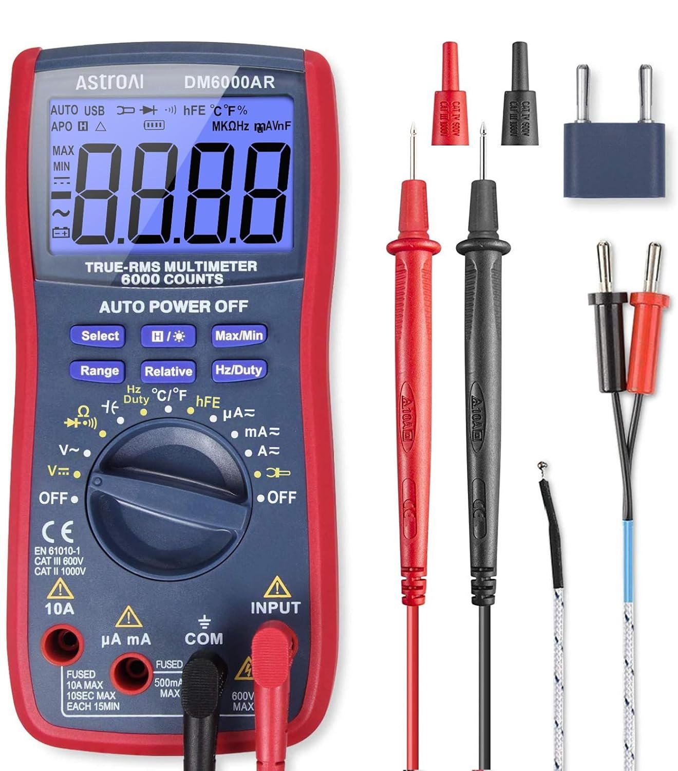
AstroAI Digital Multimeter and Analyzer TRMS 6000 Counts Volt Meter Ohmmeter Auto-Ranging Tester; Accurately Measures Voltage Current Resistance Diodes Continuity Duty-Cycle Capacitance Temperature
Buy on Amazon As an Amazon Associate I earn from qualifying purchases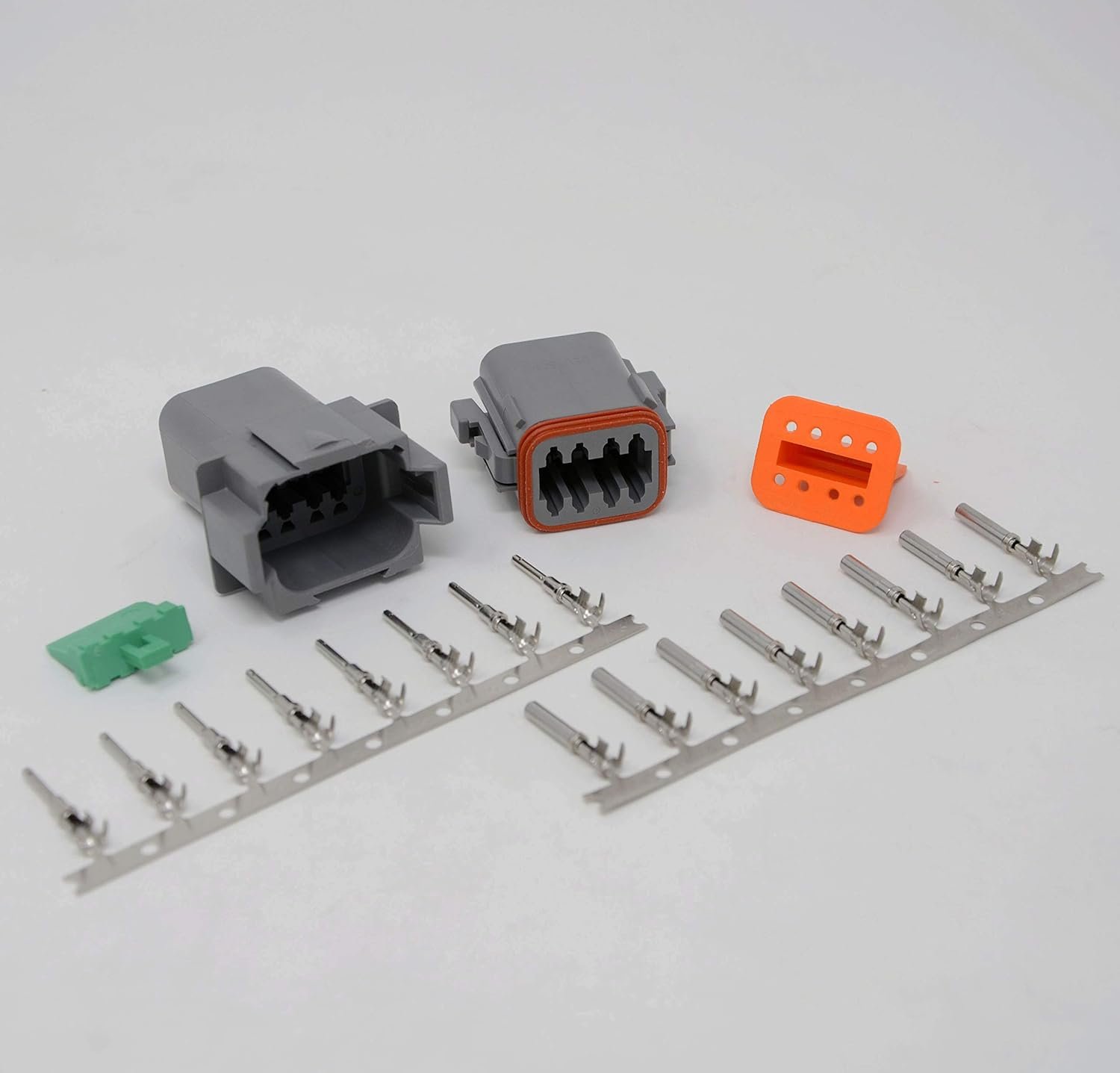
Deutsch 8-pin Connector Kit W/housing, Terminals, Pins, and Seals 14-16 Gauge Crimp Style Terminals
Buy on Amazon As an Amazon Associate I earn from qualifying purchases
400 Pcs Heat Shrink Tubing Kit-3:1 Ratio Adhesive Lined,Marine Grade Shrink Wrap - Industrial Heat-Shrink Tubing - Black
Buy on Amazon As an Amazon Associate I earn from qualifying purchases
SVAAR 380PCS Non Insulated Butt Connectors Kit Butt Splice Connector Uninsulated Wire Splice Connectors for 26 to 6 Gauge Wire Marine Grade Tinned Copper Seamless Barrel Crimp Butt Splice Terminals
Buy on Amazon As an Amazon Associate I earn from qualifying purchases
8Pcs Crimping Tool Kit for Heat Shrink Terminals, Non-Insulated, Open Barrel, Solar Conncetors, Insulated and Non-Insulated Ferrules
Buy on Amazon As an Amazon Associate I earn from qualifying purchases
AstroAI Digital Multimeter and Analyzer TRMS 6000 Counts Volt Meter Ohmmeter Auto-Ranging Tester; Accurately Measures Voltage Current Resistance Diodes Continuity Duty-Cycle Capacitance Temperature
Buy on Amazon As an Amazon Associate I earn from qualifying purchases
Deutsch 8-pin Connector Kit W/housing, Terminals, Pins, and Seals 14-16 Gauge Crimp Style Terminals
Buy on Amazon As an Amazon Associate I earn from qualifying purchases
400 Pcs Heat Shrink Tubing Kit-3:1 Ratio Adhesive Lined,Marine Grade Shrink Wrap - Industrial Heat-Shrink Tubing - Black
Buy on Amazon As an Amazon Associate I earn from qualifying purchases
SVAAR 380PCS Non Insulated Butt Connectors Kit Butt Splice Connector Uninsulated Wire Splice Connectors for 26 to 6 Gauge Wire Marine Grade Tinned Copper Seamless Barrel Crimp Butt Splice Terminals
Buy on Amazon As an Amazon Associate I earn from qualifying purchases
8Pcs Crimping Tool Kit for Heat Shrink Terminals, Non-Insulated, Open Barrel, Solar Conncetors, Insulated and Non-Insulated Ferrules
Buy on Amazon As an Amazon Associate I earn from qualifying purchasesClick here for printable PDF. The pinout for manual and auto IS300 is listed side-by-side.
| A | M | ||||
| Pin | Color | Purpose | |||
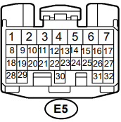
| E5 Connector "C on diagram" | 1 | W-B | Gnd. F. Intake (joins E6-7 BR) | ||
| 2 | W-B | ||||
| 3 | BR | Gnd, c. intake (joins E7-4) | |||
| 4 | |||||
| 5 | |||||
| 6 | |||||
| 7 | B-L | Igniter pin4. IGF | |||
| 8 | |||||
| 9 | |||||
| 10 | |||||
| 11 | |||||
| 12 | |||||
| 13 | GR-B | Igniter pin7. IN1 (looks light brown) | |||
| 14 | |||||
| 15 | B-W | Injector 6 | |||
| 16 | R-W | Injector 4 | |||
| 17 | L | Injector 2 | |||
| 18 | |||||
| 19 | |||||
| 20 | |||||
| 21 | Y-G | VSV #2 ACIS(discolored looks L-Brown) | |||
| 22 | Y-R | VSV #3 Canister closed(discolored as above) | |||
| 23 | V | P/S pressure signal | |||
| 24 | R | Coolant temp sensor | |||
| 25 | |||||
| 26 | L-W | MAF | |||
| 27 | G-B | MAF (looks blue) | |||
| 28 | (B) | O2 B2S1 signal | |||
| 29 | |||||
| 30 | P | O2 B2S1 heater | |||
| 31 | |||||
| 32 | L-B | MAF | |||
| A | M | ||||
| Pin | Color | Purpose | |||
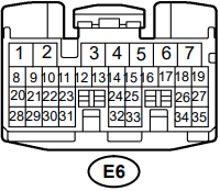
| E6 Connector "D on diagram" | 1 | (B) | Knock 1 | ||
| 2 | (W) | Knock 2 | |||
| 3 | G-R | A/T Neutral position | |||
| 4 | G-W | A/T 2L position | |||
| 5 | R-B | A/T Reverse Position | |||
| 6 | G | A/T P position | |||
| 7 | BR | Gnd Front Intake (shield gnd) Joins E5-1) | |||
| 8 | |||||
| 9 | LG | O2 B1S1 heater (light green) | |||
| 10 | LG-B | SLU- | |||
| 11 | G-W | SLU+ | |||
| 12 | R-W | SLN- | |||
| 13 | Y-R | SLN+ | |||
| 14 | W-R | Oil Level Sensor | |||
| 15 | L-R | Alternator pin 1 | |||
| 16 | B-R | S4 | |||
| 17 | W-L | S3 | |||
| 18 | G-Y | S2 | |||
| 19 | Y | S1 | |||
| 20 | G | NCO-(O/D direct clutch spd sensor | |||
| 21 | R | NCO+(O/D direct clutch spd sensor | |||
| 22 | R-L | SP2-(Vehicle Speed Sensor) | |||
| 23 | L-Y | SP2+(Vehicle Speed Sensor) | |||
| 24 | |||||
| 25 | |||||
| 26 | |||||
| 27 | |||||
| 28 | (W) | O2 B1S1 signal (discolored, looks pink) | |||
| 29 | |||||
| 30 | |||||
| 31 | |||||
| 32 | |||||
| 33 | |||||
| 34 | R-B | SLT- | |||
| 35 | B-Y | SLT+ | |||
| A | M | ||||
| Pin | Color | Purpose | |||
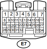
| E7 Connector "E on diagram" | 1 | B-W | Shield for TCM M-,M+ (tape covered) | ||
| 2 | R | Throttle (TCM M-) (CAUTION! See pin 15) | |||
| 3 | W | Throttle (TCM M+) | |||
| 4 | BR | Gnd, center intake (joins E5-3) | |||
| 5 | Y-B | VVTi- (looks tan) | |||
| 6 | R-Y | VVTi+ | |||
| 7 | GR | Oil Press Sw | |||
| 8 | L-B | From Rad Fan | |||
| 9 | Y | Throttle (TCM C-) | |||
| 10 | R-W | Throttle (TCM C+) | |||
| 11 | W-G | VSV #4 Evap | |||
| 12 | |||||
| 13 | L-R | Injector 5 | |||
| 14 | V | Injector 3(discolored looks L-brown) | |||
| 15 | R | Injector 1 (CAUTION! See pin 2) | |||
| 16 | |||||
| 17 | |||||
| 18 | |||||
| 19 | |||||
| 20 | |||||
| 21 | |||||
| 22 | |||||
| 23 | |||||
| 24 | G-Y | TPS VTA2 | |||
| 25 | W-R | TPS VTA1 | |||
| 26 | B-Y | Igniter pin5. IN3.to IGNpin 10 | |||
| 27 | B-R | Igniter pin6. IN2.to IGNpin 2 | |||
| 28 | |||||
| 29 | (G) | Cam Sensor | |||
| 30 | |||||
| 31 | (B-W) | Crank Sensor | |||
| 32 | (L) | Cam/Crank (-) joined | |||
| 33 | |||||
| 34 | W-L | A/C magnetic clutch and lock sensor | |||
Click for additional 2JZ IS300 ECU resources like wiring diagrams and pinouts.