IS300 ABS ECU sensors, switches and Cluster lights
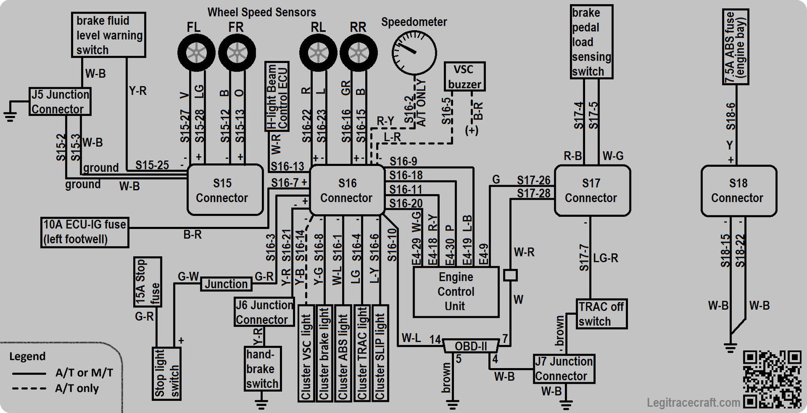
IS300 ABS wire pinout
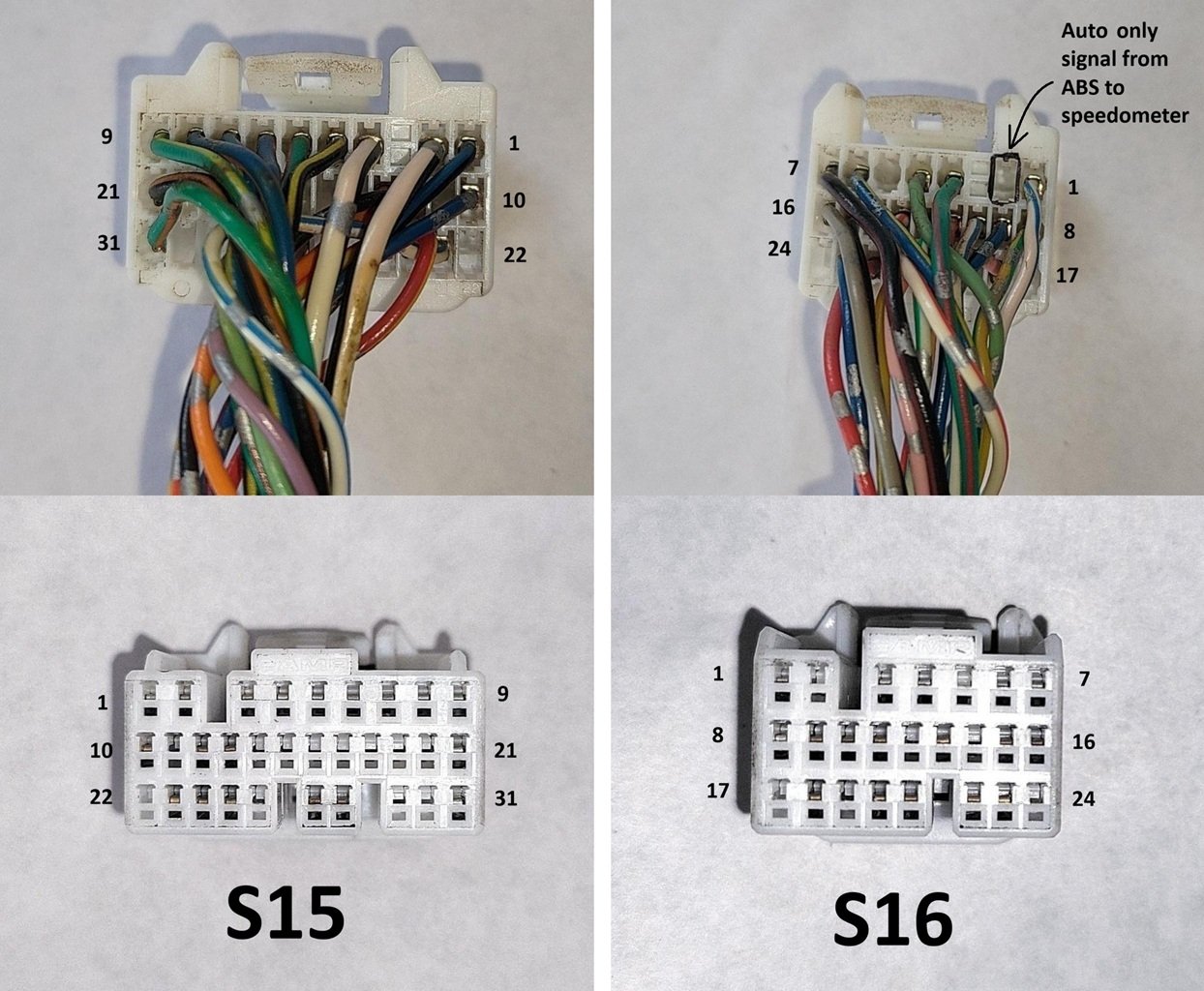
Inputs & Outputs when using the ABS Bypass header
The S15 and S16 connector bypass "pin header/ECU header":
By making the bypass harness you can wire your speed sensors directly into your engine management, wire any of the 4 cluster lights to a ground switched output on your engine management to be used as warning lights, control both of the relays after connecting the relay positive to an ignition switched power source(like pin 7 on the S16 connector) and each negative relay trigger to your engine management's ground switched output (power something like intercooler sprayers), hand brake input for a custom no-start/homemade immobilizer, and the rest of the wires that previously routed to the actuator, the engine ECU, OBD2 or brake fluid level switch can be used for anything that their 18/20AWG wires can handle. Best of all, this can be wired on a workbench so you're not laying in your floorboard crimping and heatshrinking wires!
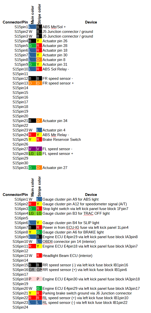
ABS Connectors S15 & S16 Pinout (Reusability)
On the left is the pinout of the two primary ABS connectors (S15 and S16). If your goal is to reuse these wires, wire the sensors into your engine management, or connect to the lights on your gauge cluster, you'll be using these pins.
The only major exception is the TRAC-OFF switch wire, which connects to connector S17. The device and pin they used to connect to is listed below on the S17 connector.
Other than this, the majority of the wires that feed into the engine bay connect to connectors S15 and S16.
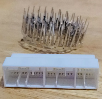
The GREAT NEWS is that these two connectors are also used on several K Series Honda applications & NB Miata. Which means you can buy a header panel like the one pictured below, connect your wires to the wheel speed sensors, gauge cluster lights, and whatever extra you have in your engine bay after you pull the wires from the ABS actuator plug, then plug in these two plugs to the header panel. That's it!
This is especially exciting since the ABS ECU connectors are highly difficult to crimp and heatshrink (due to their location under the dash).
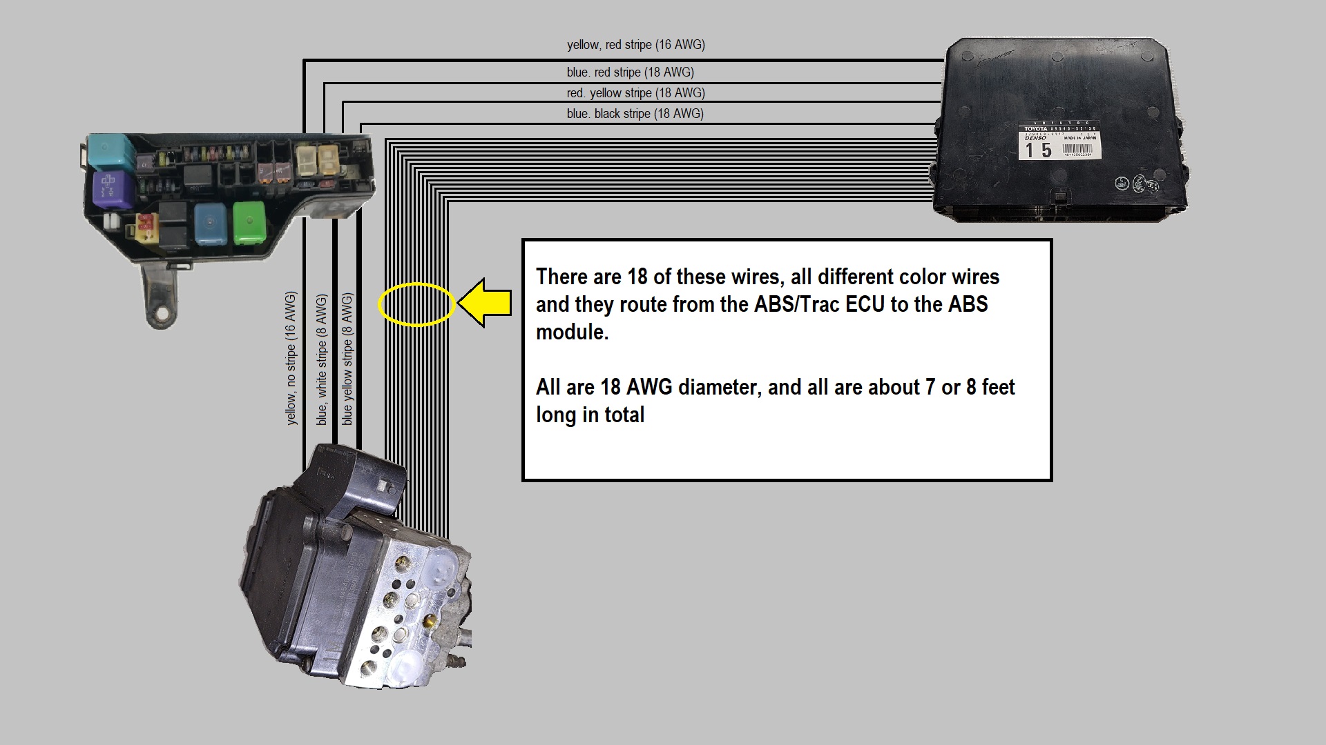
19 of the wires in the graphic on the left go straight from the ABS ECU to the engine bay.
90980-11421 — S15
90980-11476 — S16
89540-53150 — ABS & Trac ECU
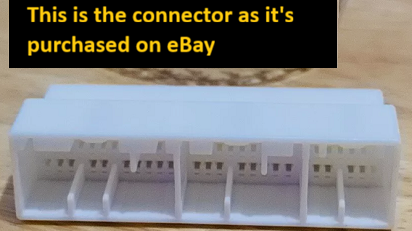
Picture below is from eBay. You can click here I've set up the NB Miata search for you. Ballenger Motorsports has a breakout board as well that is more expensive, and likely better quality than this eBay example, but since it's a breakout board and not a pin header it would require soldering each wire to and potentially protecting the solder joints from arcing on metal nearby (thus more difficult).
Reusing the wires/fuses/or relays in the engine bay
Repurposing ABS Wires in the Engine Bay
If your goal is to repurpose the wires, the below graphic shows the wire routing in the engine bay that can potentially be used to connect to whatever you want to connect them to.
If you extend these wires using the above pin guide, you can potentially wire them to your engine management, PDM, or whatever other device you have.
As stated above, connectors S15 and S16 on the ABS ECU are also used on a Honda, and the pin header can be purchased online.
The pin header can be used as a jumper to connect to an engine management system — so most of the wires going through the firewall can be repurposed as engine sensor wires. A flying lead harness doesn't necessarily need to be used!
ABS Fuse & Relay Power Details
Regarding the fuses, there is a large cartridge fuse (60 amp) that feeds the ABS MTR and ABS SOL relays.
There is also a small 7.5 amp fuse that powers the ABS and Trac ECU.
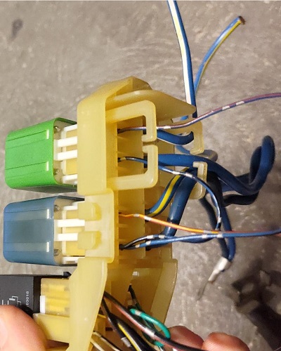
The outputs for these relays are in the diagram below:
- MTR power output: Blue with a yellow stripe
- SOL power output: Blue with a white stripe
Wire colors to note: Blue w/ yellow stripe and blue w/ white stripe.
You'll need to trigger the relays with the smaller wires that are mentioned in the paragraph to the right.
The 7.5 amp "ABS 2" fuse is technically "downstream" from the ABS relay. The power for this fuse is routed through the ABS module (block) after it receives power from the ABS MOD relay, and feeds that power back to the fusebox via the Yellow wire.
The yellow wire with the red stripe feeds the ABS and Trac ECU power. This is a 16 AWG wire, so consult how much amperage can be pulled through it before you power something. Use the appropriate fuse.
• 60A cartridge fuse → feeds ABS MTR & SOL relays
• Blue/Yellow stripe → MTR output
• Blue/White stripe → SOL output
• Yellow/Red stripe → ABS & Trac ECU power (16 AWG – size fuses accordingly)
• 7.5A ABS 2 fuse → downstream via ABS module & Yellow return wire
ABS Relay Triggers & Grounds (Post-Removal Reuse)
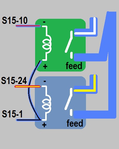
Considering you've removed the ABS system, you'll have a 60 amp fuse that feeds two relays that you can take advantage of.
The positive trigger for both relays to be powered on (coil) is the blue wire with the black stripe.
The negative wire for the ABS MTR relay is red with a yellow stripe, and the negative wire for the ABS SOL relay is blue with a red stripe.
Consult your wire diagram for more detailed information regarding the relays, fuses, and wires.
Key ABS connector pins (S15) for relay control:
- S15-10 (blue wire with red stripe) — SOL relay ground controlled by the ABS ECU
- S15-24 (red wire with yellow stripe) — MTR relay ground controlled by the ABS ECU
- S15-1 (blue wire with black stripe) — both the SOL and MTR relay positive from ABS ECU
• Positive trigger (coil +): Blue/Black stripe (S15-1)
• MTR relay ground (coil -): Red/Yellow stripe (S15-24)
• SOL relay ground (coil -): Blue/Red stripe (S15-10)
These can be repurposed to trigger auxiliary relays or devices using the existing 60A feed — just add your own fused positive/negative as needed.
MAKING THE is300 ABS ECU HEADER FROM THE K20 HEADER
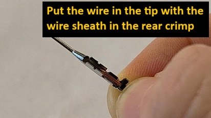
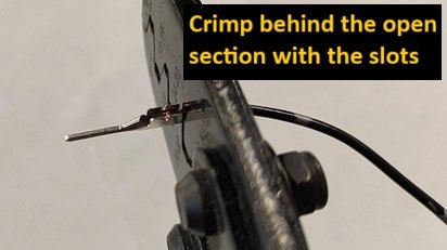
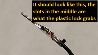
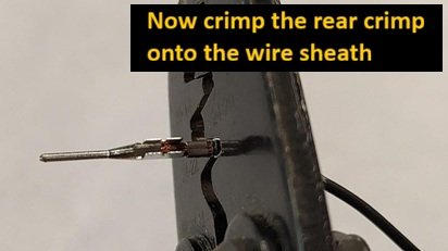
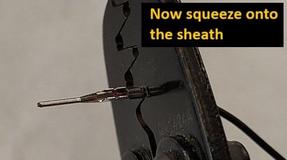
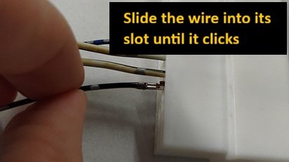
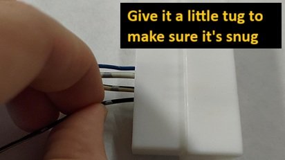
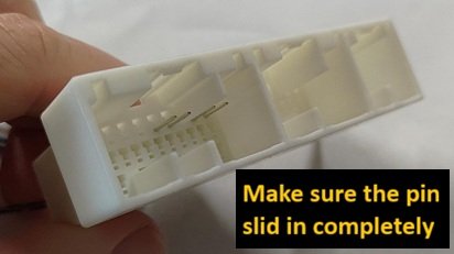
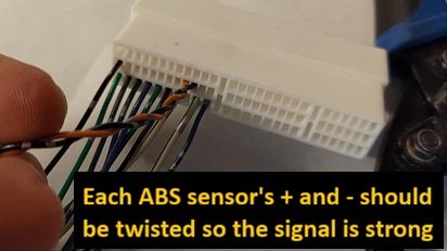
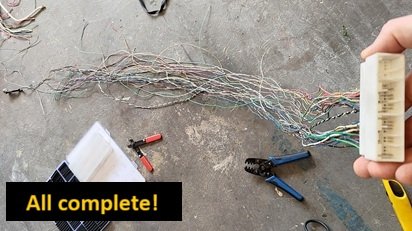
Building ABS Pin Header
Key notes for building jumper/header:
- Crimp well on copper: Crimp the copper, don't crimp the locking section, and leave some sheath on the pin to crimp it next.
- Lock pin in place: Slip the pin in and make sure it's snug (tug on it).
- Twist 2 ABS wires (+/-) around each other: This keeps the signal strong on leading to the ECU.